Срочная публикация научной статьи
+7 995 770 98 40
+7 995 202 54 42
info@journalpro.ru
Studying of forming parameters for deep drawing of carbon steel sheets
Рубрика: Физико-математические науки
Журнал: «Евразийский Научный Журнал №12 2016» (декабрь)
Количество просмотров статьи: 4875
Показать PDF версию Studying of forming parameters for deep drawing of carbon steel sheets
Ahmed Kadhuim Muhammad,
Ibrahim Abdulwahhab Atiyah,
Hamza Mustafa Kamal,
Mohammed Ali Abdulrehman,
Ahmed K. Al-kamal*
Al- Mustansiriyah University, Faculty of Engineering,
Material Engineering Department, Baghdad, Iraq.
E-mail: alexa2000sh@yandex.ru
Abstract: Deep drawing is a process in which a blank or workpiece, usually controlled by a pressure plate, is forced into or through a die by means of a punch to form a hollow component in which the thickness is substantially the same as that of the original material. In this research study, the deep drawing parameters (thickness, drawing ratio) for steel sheets type SAE 1006 that are reserved for deep drawing at the company of which this research was performed. The mechanical properties for the material were first investigated (anisotropy index, exponent of strain). The main aim of the research was to find the rupture and wrinkling curves for the steel sheets with a thickness of (1mm) and a drawing ratio of (1.81). With the aid of these curves it was possible to overcome the two main defects of deep drawing (Tearing and wrinkling). A study was also performed in which the effects of different thickness of sheets are shown by using blanks with a thickness (1.5mm). The effect of (1.5mm) and (1mm) thickness on the wrinkling curve was studied when a thickness of (1.5mm) was used the wrinkling curve was lowered thereby increasing the working zone in which deep drawing is performed. This was found by varying the blank holder force. The variation of the thickness across the final product was also studied. It was found that when the blank thickness is increased the variation of thickness along the final product will decrease. This will results in finer quality product. The effect of the drawing ratio was also inspected on the deep drawing process. Smaller blank diameter was used in order to find the effect of decreased drawing ratio on the wrinkling curve. A comparison was also made between the wrinkling curves for a drawing ratio of (1.52 and 1.81).From this it was deduced that increasing the drawing ratio would lower the wrinkling curve. As a result the area of the working zone will increase; this will improve the deep drawn product. The variation of the thickness across the final product was also studied; it was found that when the drawing ratio decreases the variation of thickness along the final product will decrease. This means better quality products.
Keywords: deep drawing, strain of exponent hardening, tearing, and wrinkling
Introduction:
Deep drawing is pressing a flat blank sheet to make a dished form, where the sheet is drawn or stretched over a die having the interior shape of the desired [1]. When this process is achieved with tools, it can be classified according to the tools used as: rigid tools, and elastic tools. In the first as an example, the single action die with single action press, and double action die with double action press and in the second as marforming, and hydroforming process. [1], [2]. The choices of tools depend on the desired shape, and economical factor. This process passed through many development stages. These developments cover three major conditions namely the metallurgical properties like work hardening exponent, grain size control, and stretcher strain. The second condition is tool design such as: die, punch, and clearance between them, blank holder, and the third condition is the operation condition as the speed of the drawing, die lubrication, and clamping force. [3].
The simple description of this process is: the (blank) is held over the opening in the die, and forced to deform by the moving ram (punch). As the ram moves downward, it pulls the flange towards the center. The flange is held between the die, and the blank holder (pressure pad) or (hold-down ring). The flange moves inward radially while its inner side bends over the rounded corner of the die, and transforms from a flat disk to a circular tube.
At this point the bottom is not deformed, while the cylinder is already deformed but is not undergoing further deformation. Also, the toroidal section between the cylinder and the flange is undergoing plastic deformation.
The flange and the toroidal section around the corner of the female die are undergoing plastic deformation. Friction prevails on the top and bottom flat surface of the flange, and on the surface of the corner radii of the female die.
Ram forces the motive power to overcome the deformation, and friction resistance. The ram force is normally transmitted from the ram to the cup through pressure on the bottom of the cup. The ram pressure is transmitted from the bottom of the cup to the deformation region through tension on the wall of the cup [4]. This tension must remain elastic in deep drawing the thickness of the deformed cup is only minutely changed while the shape of the disk is modified to that of a cup. In pure drawing the gap between the punch and the die is somewhat larger than the thickness of the incoming bent disk. The flange while moving inward is reduced in diameter and therefore tends to increase slightly in thickness. The thickening tendency of the flange is a result of the shortening of the circumference. Simply, when a change in length in one direction is effected, the dimension on the free side, normal to the forced change, is changed in the opposite sense. The final cup is slightly conical in shape. This is because the bottom that contacts the ram is slightly smaller than the top, which conforms to the larger size of the opening of the die at the top. As soon as the cup is pushed clear of the die, the open —end springs back slightly as the elastic portion of the deformation is released. The thinning near the bottom is undesirable, it is associated with an excessive drawing force, and in most deep drawing operations is prevented. [4].Sheet metal parts manufactured by press working may contain defects due to :- defective sheet stock, incorrect punch, and die design, and incorrect press work techniques. Some of the defects encountered in sheet metal formed parts are: — stretcher strain marks, orange peel effect, earing, sinking, burr and bend, tearing, part failure, and wrinkling.
Previously, during the design stage of the die for deep drawing, constant pressure blank holder was assumed during the punch travel. However, recent work in deep drawing using a hydroforming process (yossifon [5]) , shows the actual diagram, which consist of two curves the first curve or the upper curve or the rupture curve, and the lower curve or the wrinkling curve (buckling curve). The rupture and the wrinkling curves shows the two major defects in deep drawing process, the first one is caused by the tensile forces which exceed the maximum tensile strength of the material; the second is caused by the hoop stress on the flange, This is produced when the blank holder force is insufficient to hold it tight, and cause plastic flowing to the die opening. There are some parameters, which have an affect on these curves, some of these parameters have an effect on the rupture curve, such as drawing ratio, friction, and speed of punch, Other factors which have an effect on the wrinkling curve are; sheet thickness and strain hardening exponent. [6, 7]. This study has been conducted to establish these curves study also shows the effect of thickness change on the wrinkling curve [8].
Experimental work:
The metal that was used in this research consisted of sheet of low carbon steel ,SAE1006 with two thicknesses (1mm, 2mm) no surface coating was applied .the low carbon steel that was evaluated is AL-KILLED,COLD ROLLED steel sheet. Table (1) shows the chemical composition.
Table 1 The chemical compositions
| Designation DIN 17006 | SAE | C | Si | Mn | P | S | Al | N | element |
| RRSt-14 | 1006 | ≤0.08 |
|
≤0.04 | 0.025 | 0.025 | ≤0.02 | ≤0.007 | % composition |
1. Anisotropy index calculation:
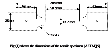
The tensile specimens that were prepared depended on the dimensions, which are shown in figure (1)[9].this was done so as to measure the anisotropy index (r ) ,Δr, and ravg .these are considered important factors that have a significant effect on the drawability of the metal; by tense these specimens on the tension tester device . These specimens were taken at the (0,45,90) degrees from the rolling axis and strained to
Table (2) show the values of (r ) in three directions Table (3) the value of ravg and![]()
| ravg | 1.57 |
| Δr | 0.54 |
| r0 | 1.73 |
| r90 | 1.92 |
| r45 | 1.23 |
2. Exponent of strain hardening calculation:
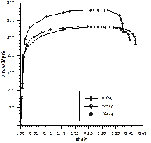
In deep drawing, the work hardening exponent is a major factor in the operation; therefore it should be evaluated experimentally, for the blank material that is to be drawn. Tensile test specimens were cut from the material, to the dimensions stated in figure (1). Three specimens were cut for each of the following a parallel to the rolling direction, perpendicular to the rolling direction, and at 45 degree from rolling direction. the results were plotted on engineering stress-strain curve for each direction, comparison between these curves is shown in figure (2).then these curves were covered to the log true strain- log true stress curve to calculate the the (n) values which are shown in table (4).
| Angle to rolling direction | 0˚ | 45˚ | 90˚ | ||
|
The (n) value
|
0.35 | 0.33 | 0.32 | ||
| Average of (n) | 0.33 | ||||
Table (4) show the results of exponent of strain hardening
Figure (2) the comparison between
three directions specimens results
3. Deep drawing test
The final aim is to establish the boundaries of the wrinkling and rupture zones when using AL-KILLED STEEL SAE1006.using 100 ton hydraulic press for single action type as seen in figure (3), and the die which is used shown in figure(4). Spring blanckholder system with two different stiffnesses 48 and 96 N/mm was used to applied the blank holder force. The drawn black has 145 mm diameter with 1 mm thickness, while the punch diameter was80 mm and the die diameter was 82.5 mm, which giving a drawing ratio equal to 1.81.
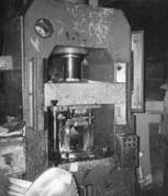
Figure (3) 100ton hydraulic press
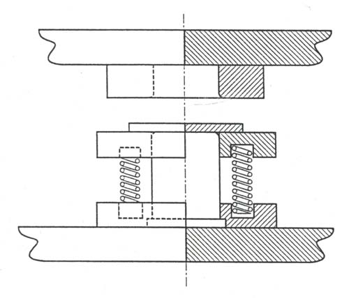
Fig(4) Hydraulic Single Acting Die.
The test commenced by using pre- compressed spring system such as the blank holder being on the same level as the punch surface; this will give a pressure of (4×48=192 N). When we used the springs that had stiffness (48N/mm) to show the wrinkling and working zones, wrinkling started after (24mm) punch travel at (12mm) pre- compress. To delay wrinkling initiation, the blank holder level was raised above the punch by a further (1.5mm), using spacer plate (washer) on the top of the spring that was used .this would give a path force parallel to the first. Wrinkling appeared at (27 mm) punch travel. Another experiment was preformed using pre- compression of (14mm) and wrinkling delayed to the depth of (43.5 mm). a total of (4) tests were made with different pre- compressions springs with (96N/mm)stiffness ,the initial pressure was (8×96=768 N) and without the use of spacing showed the rupture zone. Rupture started after (27.5mm) punch travel. To accelerate rupture initiation, the blank holder was raised above the punch by a further (3mm), using spacer plate (washer) on the used spring. This gave a path force parallel to the first and rupture appeared at (23.5mm) punch travel. Another experiment was done using pre- compression of (16mm) and the rupture was accelerated to the depth (17mm). a total of (4) tests were made with pre- compressions. The results are presented in tables (5) and (6) and these tables are graphically in figure (5).
Table (5) the results of deep drawing test using spring has stiffness (48N/mm)
| No. of specimen | Pre-compress Of springs(mm) | Depth of cup(mm) | Results |
| 1 | 12 | 24 | Wrinkling |
| 2 | 13.5 | 27 | Wrinkling |
| 3 | 14 | 43.5 | Wrinkling |
| 4 | 15 | 46 | Good |
The spring used to show the rupture has stiffness =96 N/mm, No. of springs were 8
Table (6) the results of deep drawing test using spring has stiffness (96N/mm)
| No. of specimen | Pre- compress of spring(mm) | Depth of the cup(mm) | Results |
| 5 | 0 | 27.5 | Slight rupture |
| 6 | 3 | 23.5 | Rupture |
| 7 | 16 | 17 | Rupture |
| 8 | 24 | 14.9 | Rupture |
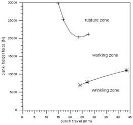
Figure(5) show the rupture ,wrinkling and working zones
4. The effect of thickness change on the wrinkling curve:
This test preformed by using pre- compressed spring system with blank holder level at (1mm) higher than the level of punch , this will give a load (2928 N). Wrinkling started at (14.25mm) punch travel. To delay the wrinkling initiation, the blank holder level was raised above the punch level by further (2mm) using spacer plate on top of springs. The wrinkling appeared at (22.25mm) punch travel. Another experiment was done using pre- compression of (3.5mm); the wrinkling was delayed to the depth of (42.5mm).the results are in table (7). The rupture curve is not appearing because of
Table (7) the results of effect of using blanks with (1.5mm) thickness on the wrinkling curve
| No. of specimen | Pre-compress of spring(mm) | Depth of cup (mm) | Results |
| 1 | 1 | 14.25 | Wrinkling |
| 2 | 3 | 22.25 | Wrinkling |
| 3 | 3.5 | 42.5 | Wrinkling |
| 4 | 4 | 48 | Good |
the limited length of the springs. Table (7) graphically shown in figure (6) and the comparison between 1mm and 1.5 mm blank thickness was shown in figure (7)
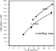
Figure (6) effect of thickness change on wrinkling zone
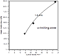
Figure (7) show the comparison between (1mm, 1.5mm) thicknesses on wrinkling zone
5. Drawing ratio effect on the wrinkling curve:
In this test the effect of drawing ratio investigated .the test was preformed by using pre-compressed spring system as blank holder was higher than the punch level by (3mm), this will give load equal to 5340N the wrinkling started after (19.25mm) punch movement ; as previous to delay the wrinkling happens the blank holder level was raised above the punch by further (3.5mm) using a washer on the top of springs .this would give a path of force parallel to the first one ,wrinkling appeared at (21.5mm) punch travel. Another experiment was preformed using pre compression of (4.5mm) and wrinkling was delayed to the depth (30.25mm). From these experiments it can be draw the wrinkling curve. The results in table (8). A comparison with the original drawing ratio was shown in figure (8).
Table (8 effect of using blanks with 126mm diameter on the wrinkling curve)
| No. of specimens | Pre-compress of spring(mm) | Depth of cup (mm) | Results |
| 1 | 3 | 19.25 | wrinkling |
| 2 | 3.5 | 21.5 | wrinkling |
| 3 | 4.5 | 30.25 | wrinkling |
| 4 | 5 | 32.6 | good |
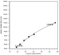
Figure (8) show the comparison between (1.81,1.52)D.R. on wrinkling zone
Results and discussion:
The results obtained from the experiments conducted in the present work indicate that the work hardening exponent (n) has values (0.353, 0.337, and 0.32) and the value of the anisotropy index(r ) has values (1.77,1.29, and 1.91)for the different directions(0,45,and 90) degree respectively. The value of (n) in rolling direction and (r ) perpendicular to the rolling direction are larger than the others directions .the work hardening exponent connecting with good strength and ductility , gives a good formability , and its a factor which controlling the necking in deep drawing process. The value of ravg. and Δr were(1.57, and 0.54)respectively refer to good drawability for the metal [10]the index ( r ) is considered one of the most important factors in deep drawing process because the anisotropy factor(r )affects the magnitude of the limiting drawing ratio .with increasing values of (r ) and ravg the value of limited drawing ratio also increase since the force required for tearing the bottom of the deep — drawn cup also increase with (r )and ravg and the total draw force required decreases. Sheet metal with good deep drawing characteristics should have high (r ) or ravg and a small planar anisotropy Δr [10]. To establish the three important zones (rupture, wrinkling, and working), a system of springs was used as a blank holder. The force line of the springs is goes up by inclined path therefore in this system we can obtain longer depth for the products ,which means higher drawing ratio than the hydraulic system ,because in the second system the line of the applied force have a horizontal path in the blank holder force- punch travel diagram, which means that any shift in any one of the wrinkling or rupture curves may be crossing the force line and leading t the failure [1,2,3].seats of experiments were done to check the effect of changing of the blank thickness on the deep drawing process the results of these experiments are shown in table (6) .from the comparison between tables (5) and (6) , it is shown that the deeper successfully drawn was with blank has a thickness of (1.5mm) it reached to (48mm) while in thickness(1mm) reached to (46mm). as it was expected that boundary of the wrinkling zone would shift downwards, which make the working zone larger as shown in figure (7). Therefore an increase in thickness of the blank would give a higher chance to drawing the cups without wrinkling this is due to decrease in hoop stresses. A number of blanks with the diameter (126mm), and (1mm) thickness was prepared to show the effect of drawing ratio. Then these blanks are drawn with the same condition to that were used had a stiffness (60N/mm).the results are sown in table (8). From the comparison between the graph of the blank with diameter of 126 mm and blank with diameter 145mm figure (8), it was clearly shown that with small drawing ratio we need a lower blank holder force to obtain a good product. From a comparison between good products for the original drawing ratio with new drawing ratio it was remarked that the cup with smaller drawing ratio has a more homogenous thickness along the cup than the cup which had a larger drawing ratio. And the earing phenomena was reduced with
Convolutions:
1. As the blank thickness increases, the wrinkling curve will be shifted downward, hence increasing the safe working zone.
2. The increase in thickness would be give deeper products.
3. When the thickness of the blanks increases the variation in thickness along the products reduced.
4. Reducing the drawing ratio will shift the wrinkling curve down ward also, and increasing the working zone.
5. When the drawing ratio reduced, the variation in thickness will be reduced along the product.
6. When the drawing ratio reduced the earing is also reduced.
References
- Roger W. Boltz “Metals Engineering Processes”. ASME Handbook. First edition. Publ. McGraw-Hill, 1958.
- Kut. Lange “Handbook of Metal Forming”. Publ. McGraw-Hill, 1985.
- Ammar A. Mohammed “A study Into Deep Drawing Parameters of sound products”. M. Sc Thesis Submitted to Baghdad University/ Mechanical Dept., 2000.
- Avitzur, B. “Handbook Of Metal Forming Process”, John — wiley and sons, New York, 1976.
- S. Yossifion and J. Tirosh “The Maximum Drawing Ratio In Hydroforming Processes”. Int. J. Mech. Sci. Vol. 112, P
47-55, 1990. - S. Yossifion and J. Tirosh “Rupture Instability in Hydroforming Deep Drawing Process”. Int. J. Mech. Sci. Vol. 27, No. 9, P
559-570, 1985. - S. Yossifion and J. Tirosh “on suppression of plastic buckling in Hydroforming process”. Int. J. Mech. Sci. Vol. 26, No.
6-8, P389-402, 1984. - Satoh, S. “Effect Of Alloying Element And Hot-Rolling Condition On The Mechanical Properties Of Continuos Annealed, Extra-Low-Carbon Steel” Pup. By metallurgical SOC of AIME. Warrendale, PA, USA. P151-166, 1985.(cited)
- ASME “Metal Handbook”, material selection and properties, vol. 1, 8th Edition, 1948.
- R. A. Higgins “Engineering Metallurgy”. Pub. Hodder and Stoughton. 5th Edition, England, 1983.

